Click the added Relay Output driverand click the Driver Editor tab.
Open the Driver Settings expander.
A description for the driver displays. It can be edited.
In the Configuration Properties expander, do the following:
In the Device Request Timeout field, enter 10000 (default value is10000 ms).
In the Check Status Rate field, enter 30000 (default value is30000 ms).
In the Notification Integration expander, do the following:
In the Batch Size field, set the value as 10 (default is 100). Batch size specifies the size in which the request is processed by the driver. The batch size displays the number of devices to which Notification interacts in one instant. For example, if there are 100 devices on which a message has to be displayed and a batch size of 10 is entered, Notification will send the message to batches of 10 devices each.
In the ExpecteddeliveryTime field, enter the time in seconds. The default expected delivery time is 10 seconds. NOTE:Notification does not guarantee the message delivery will be completed within the time entered here. This value is solely used to compute delivery statistics indicating whether message delivery to Twitter was on-time or late.
The ServiceHost field displays automatically and cannot be edited.
Click Save.
The parameters are configured for the Relay Output driver.
The Object Configurator tab displays in the Primary pane.
Click New Object and select New Relay Output Field Network.
The Create New Object dialog box displays with the Child type field pre-defined as Relay Output Field Network.
Enter a name and description.
Click OK.
The Relay Output Field Network node appears under the Field Networks node.
The Relay Output driver is automatically associated to the field network. In the Network Editor tab, under the Network Settings expander, you can see that the values are preselected, and the driver is already assigned.
Select Project > Field Networks > Relay Output Field Network.
In the Network Editor tab, click Create.
In the New object dialog box, enter a name and description.
Click OK.
Open the Device Settings expander.
Enter a description for the device.
Open the Configuration Properties expander.
In the Serial Port Number field, enter the virtual COM port number created by the TruePort driver to communicate with the Perle device. A prefix of COM should be used, so that the final value displays as COM102. NOTE: To check the COM ports that were used by the device, open the True Management tool.
From Device Mode drop-down list, select Operational.
In the New object dialog box, enter a name and description.
Click OK.
Open the Device Settings expander.
Under Device Settings, enter a description for the device.
Open the Configuration Properties expander.
Set the RelayNumber to the relay used for this device.
Do one of the following:
Leave the Enable Time Limited Activation check box unselected to operate the relay in Latch Mode, which means that the relay remains activated as long as at least one message is active for the device.
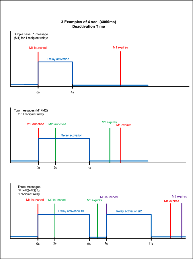
Select the Enable Time Limited Activation check box to operate the relay in Time Limited Activation Mode, which means that after every activation the relay will automatically deactivate after the specified Deactivation Time (see the Figure below).
Set the DeactivationTime to a number greater than zero and less than 3.600.000 (in milliseconds), depending on the requirements of the external device. NOTE: Set the deactivation time only if a pulsed output is required.
Click Save.
The Relay device configuration details are saved. NOTE: If the user does not select the Enable Time Limited Activation check box, the relay will remain active only for the duration of the notification (expiration time).
 and select New Relay Output Driver.
 .
. and select New Relay Output Field Network.
 .
. .
.
 .
.