In System Browser, select Adaptive Display Driver.
Click the Driver Editor tab.
(Optional) In the Driver Settings expander, modify the description.
In the Configuration Properties expander, proceed as follows:
In the Device Request Timeout field, enter 10000.
In the Check Status Rate field, enter 60000
In the Notification Integration expander, proceed as follows:
In the Batch Size field, set the value as 10 (default is 100). Batch size specifies the size in which the request is processed by the driver. The batch size displays the number of devices to which Notification interacts in one instant. For example, if there are 100 devices on which a message has to be displayed and a batch size of 10 is entered, Notification will send the message to batches of 10 devices each.
In the ExpectedDeliveryTime field, enter the time in seconds (default is 5 seconds). NOTE: Notification does not guarantee the message delivery will be completed within the time entered in the ExpectedDeliveryTime field. This value is solely used to compute delivery statistics indicating whether message delivery to the AND Display Device was on-time or late.
Click Save.
The parameters are configured for the AND Display driver.
The Object Configurator tab displays in the Primary pane.
Click New , and select NewAND Display Field Network.
In the New object dialog box that displays, proceed as follows: a. Enter a unique name and description. b. Click OK.
The AND Display field network is created in the fieldnetworks hierarchy and is selected by default.
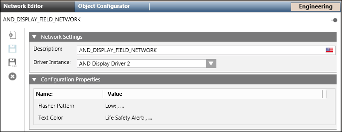
The AND Display driver is automatically associated to the field network. In the Network Editor tab, under the Network Settings expander, you can see that the values are preselected, and the driver is already assigned.
Select Projects > Field Networks > AND Display Field Network.
Open the Configuration Properties expander.
Enter the Flasher PatternValue. NOTE: The Message Priority is directly linked to the displayed Flasher Pattern. For example, for a High priority message, set the Flasher Pattern to FFF100. Make a combination of this in sequence:[Left Flasher][Middle Flasher][Right Flasher][Brightness] Flasher pattern [F/C/S/O][ F/C/S/O][ F/C/S/O][ 0-100/dim/very dim/ultra dim/bright] where C/1=ON,O/0=off , F=Fast Blink, S=Slow Blink For example, Valid Pattern includes FFF100 meaning that all the flashers (left,middle,right) blinks very fast with 100% of brightness. If the Disable Flashing check box (in the Configuration Properties expander) is not selected and the configured Flasher Pattern is incorrect, the message delivery to the AND device fails.
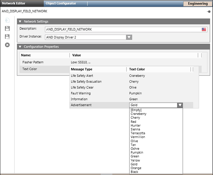
Select the appropriate text color for the various message types.
Click Save .
The AND display driver is added to the field network hierarchy.
Select Projects > Field Networks > AND DisplayFieldNetwork.
Click the Network Editor tab.
Click Create.
In the New object dialog box, enter a Name and Description.
Click OK.
Click the Device Editor tab.
In the Device Settings expander, enter a description for the device.
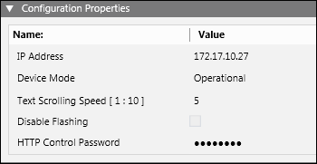
In the Configuration Properties expander, proceed as follows.
In the IPAddress field, enter the IPaddress or the hostname of the AND device.
From Device Mode drop-down list, select Operational.
Set the TextScrollingSpeed to 5.
(Optional) Clear the Disable Flashing check box. NOTE: For the hardware devices that do not support flashers, select the Disable Flashing check box.
In the HTTP Control Password field, enter the password which is set on AND web interface. Both the passwords must be identical. NOTE: While upgrading the project, the user has to set the password for the configured device.
 and select New AND Display Driver.
 .
. , and select New AND Display Field Network.
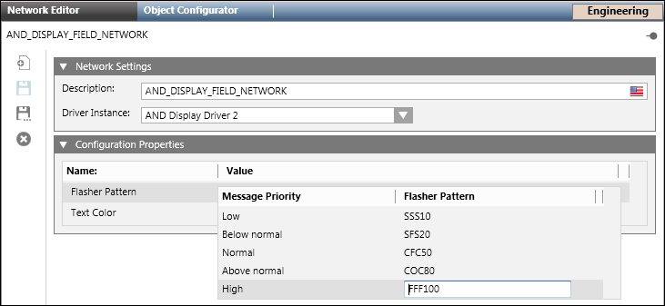
 .
.
 .
.