Creating and Configuring VoIP Switch
Scenario: You want to configure the VoIP Switch.
Reference: For background information, see the reference section.
Workflow diagram:
Prerequisites:
- System Manager is in Engineering mode.
- System Browser is in Management View.
Steps:
- The device is automatically set for DHCP and is only configurable through a web interface. To determine the IP address, work with the site IT admin to determine the leased IP address based on the MAC address of the VoIP gateway. Alternatively, the IT admin can reserve an IP address based on the device’s MAC address prior to installation.
NOTE: If there is no DHCP server on the LAN, the Vega’s IP address will default to 136.254.x.y, where x and y are the decimal versions of the last two bytes of the LAN interface MAC address.
- To log into the device, enter http://device_ip_addres/ into your web browser.
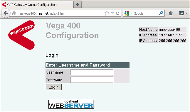
- In the Login window, enter admin in the Username and Password fields.
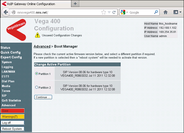
- Upon sign-in, the Boot Manager window prompts you to choose which partition to use.
NOTE: The Vega 400 can have several partitions configured for different telephony protocols. By default, the Vega 400 from Siemens should have one or more partitions all configured as SIP.
- Choose the correct SIP partition and click Continue.
- You are taken to the main System Status which gives an overview over the device configuration.
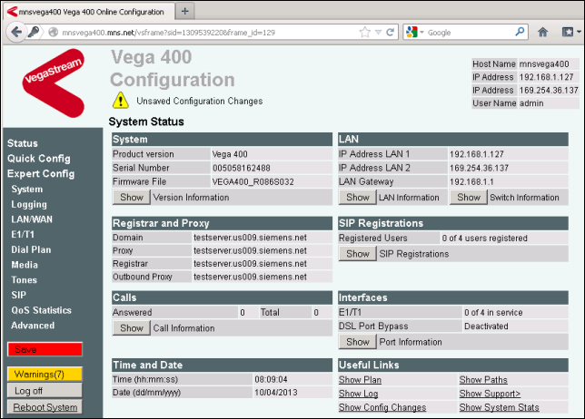
- On the main System Status page, click System on the left navigation bar.

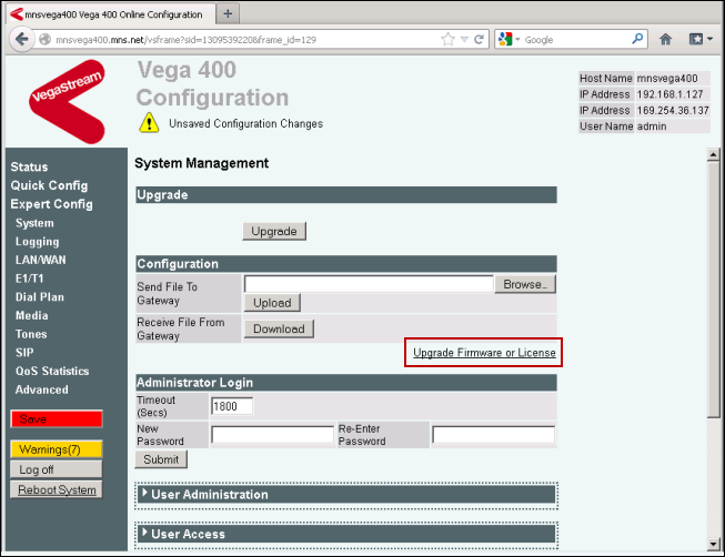
- Click the link labeled Upgrade Firmware or License.
- In the Enter New License Key field at the bottom of the page, enter your license key.
NOTE: The license is specific to the serial number of the VoIP gateway.
- Click Submit.
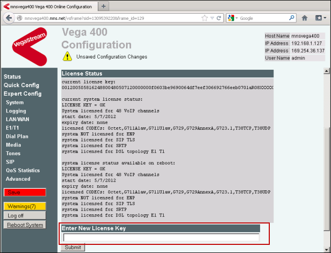
- A confirmation page displays.
- On the left-navigation bar, click System.
- Select the section labeled Administrator Login.
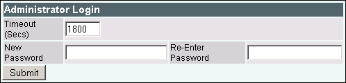
- Enter your new password and then re-enter your new password and click Submit.
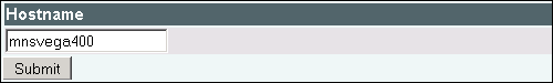
- On the left navigation bar, click LAN/WAN.
NOTE: You can change the hostname of the device in the section Hostname.
- After entering the new name, click Submit and then click here to return.
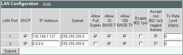
- Select the LAN Configuration section, there are two options for parameters: one for each LAN port. Verify for port 1 that the following are checked:
- DHCP
- Allow Full Duplex
- Allow 100 BASE-TX
- In the Tx Rate Limit (kbps) field make sure the value is set to 0.
- Click Submit and click here to return.
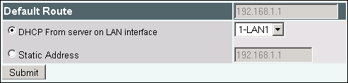
- Select the Default Route expander.
- Verify the DHCP from the server on the LAN interface and select 1-LAN1 from the drop-down menu.
- Click Submit and then click here to return.
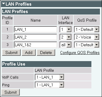
- Select the LAN Profiles expander.
- Enter the following information under Profile ID 1:
- Name: LAN_1
- LAN Interface: 1
- QoS Profile: 1 – Default
- Click Submit and then click here to return.
- Select the Profile Use expander (submenu of LAN Profiles).
- Select 1 – LAN_1 for both VoIP Calls and Ping.
- Click Submit and then click here to return.
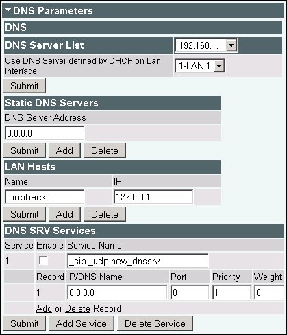
- Select the DNS Parameters expander.
- Choose the appropriate DNS server from the list. If there is more than one, contact the IT admin for the default.
- Click Submit and then click here to return.
- On the left navigation bar, click Media.
- Select Media Capability.
- Set the Voice Capability so that G711Ulaw is first in the listings as shown in the image.

- Click Submit to save the settings.
- On the left navigation bar, click SIP.
- Change the Capability Set from the default value (2-voice+t38UDP) to 1-voice as shown in the image.
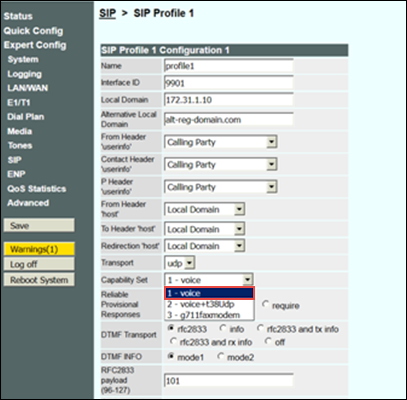
- Click Submit to save the settings.
- On the left navigation bar, click Quick Config.
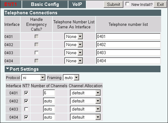
- Select the E1/T1 tab.
- Clear Handle Emergency Calls for each interface you plan to use with the external PBX.
- Select Port Settings.
- Select the signal protocol used by the external PBX. For example, NI or DMS.
- For each interface used, verify that NT is checked.
NOTE: Ports must only be configured as TE if they will connect directly to Telco (Telecommunications Company). Typically, there is a customer-owned PBX between the VoIP gateway and the Telco. As a result, the port is generally configured as NT. Check with the site's IT or telephone administrator for details.
- For each interface, enter the value for the Number of Channels assigned to that interface.
NOTE: For example, if the T1 line assigned to interface 0401 has 6 extensions/numbers associated with it, then you would enter a value of 6 for the Number of Channels.
- Select the Basic Config tab.
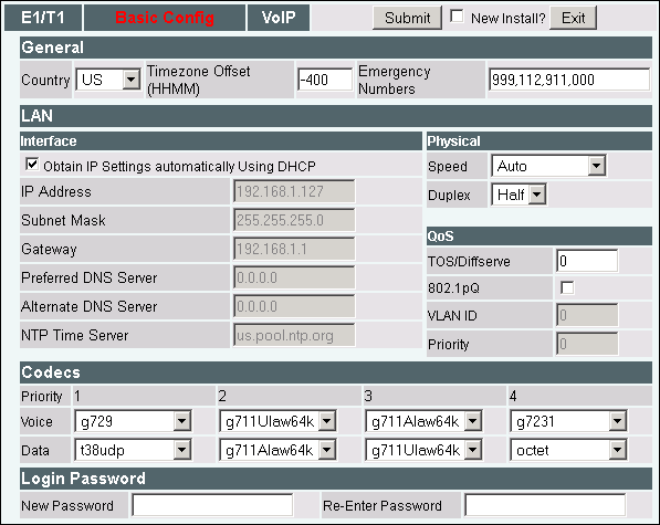
- Select the General section.
- Select your country from the drop-down list.
- Enter the Time Zone Offset of your region according to UTC.
NOTE: For example, you could enter -500 as the value.
- Select the LAN section.
- Select the Obtain IP Settings automatically Using DHCP check box, if you want the IP address to be assigned via DHCP.
NOTE: If you want to assign a static IP, clear the box and enter the appropriate values for all the fields.
- Select the VoIP tab.
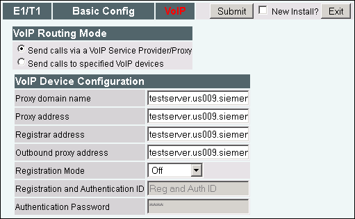
- Select Send calls via a VoIP Service Provider/Proxy.
- Select the VoIP Device Configuration expander.
- Enter the IP address of the Notification Server for the following fields:
- Proxy domain name
- Proxy address
- Registrar address
- Outbound proxy address
- Leave Registration Mode as Off.
- Click Submit.
- Select the Status expander.
- Click Save.
- Click Reboot.
- Select Expert Config > Dial Plan.
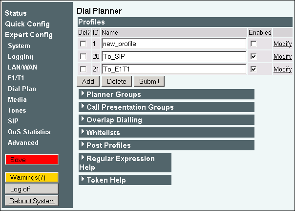
- Select the Profiles expander.
- Delete all profiles except for To_SIP and To_E1T1.
- Verify that both the To_SIP and To_E1T1 profiles are both enabled.
- Click Modify for the To_SIP profile.
- For the Source field, enter IF:040x,TEL:<.*> where x is the number of the interface needed.
NOTE: For example, if you are only using the first T1 port, enter 0401. If you are using 2 T1 ports, enter 040[1-2].
- For the Destination field, enter IF:9901,TEL:<1>,TA:ipaddress:5080 where ipaddress is the IP address of the Notification server.
- Click Submit.
- Navigate back to Expert Config > Dial Plan.
- Click Modify for the To_E1T1 profile.
- For each necessary interface, edit the Source field with IF:99..,TEL:<.*>.
- For the Destination field, enter IF:040x,TEL:<1>, where x is the number of the T1 interface calls will be sent to.
- Click Submit.
Before you can verify the functionality of the VoIP gateway, you will need to configure Notification 's VoIP Switch. Details on how to configure FreeSwitch to recognize the VoIP gateway are in the Telephony Configuration Guide.
To verify that the link between the VoIP gateway and the customer's PBX is established, do the following:
- Click Status.
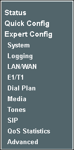
- Locate the Interfaces expander, verify that the correct number of T1 ports is in service and then click Show.
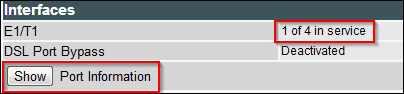
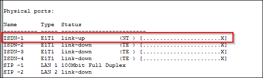
- A port status window displays.
- Verify that the status link-up displays next to each interface you are using.
In addition, test the VoIP gateway by calling and receiving outside phones calls using an IP phone registered with Notification VoIP Switch.
For details on how to configure an IP phone, refer to the IP Phone Integration Guide.
For details on how to map outside extensions to local extensions in Notification, refer to extension mapping section for VoIP gateways in the Telephony Configuration Guide.