BACnet Driver

By default, a Desigo CC project has no BACnet driver added. For procedures about BACnet drivers, including how to add one, see BACnet Driver.

Sharing a Network Interface Card

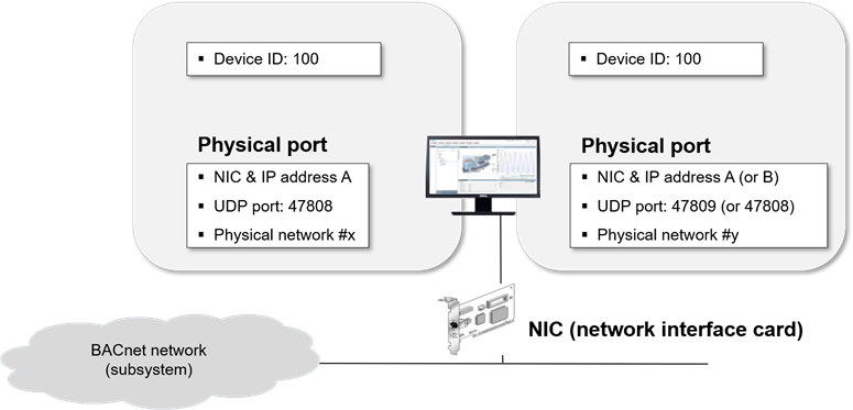
If you create more than one BACnet driver, the drivers can be assigned to the same Network Interface Card (NIC). To avoid configuration conflicts, apply the following guidelines to the physical port configuration in the BT BACnet Stack Config expander:

  • The Network Number of each Physical Port must be unique.
  • The IP Address and UDP Port (default is 47808) of each Physical Port must be unique. This means that the Physical Ports must have a different IP address or a different UDP port. For instance, if two drivers are assigned to the same NIC, you can use the value 47809 for the UDP port of the Physical Port of the second driver.

Using Separate Network Interface Cards for Each Driver

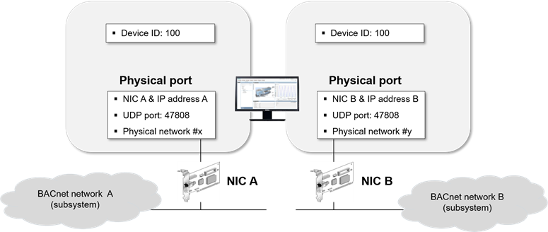
If you create more than one BACnet driver, the drivers can also be assigned to separate NICs. To avoid configuration conflicts, apply the following guidelines to the Physical Port configuration in the BT BACnet Stack Config expander:

  • The Network Number of each physical port must be unique.
  • The IP Address of each physical port must be unique. This means that the physical ports must have a different IP address.

Considerations

  • When you select the driver object in the System Browser tree, the Extended Operation tab of the Contextual pane shows its Manager Status:
    • Stopped: The driver (or the simulator) is not running. You can start the driver (or simulator).
    • Configuration Mode: The simulator started and is running properly. You can stop it.
    • Started: The driver started is running properly. You can stop it.
    • Failed: The driver (or the simulator) started but there is no connection to the Server or FEP station (for example, a station cannot be reached or is disconnected). You can stop the driver (or simulator) and then try to start it again.
  • After starting the simulator, you can continue configuring the network (for example, importing devices, and so on). To start the driver, you must first stop the simulator.
  • When the Manager Status is Failed, you cannot make changes to the configuration (for example, import operations are not allowed).
  • It is not possible to stop the driver (or the simulator) during import operations.
  • If the driver is not properly configured and you try to start it (or the simulator), the Manager Status becomes Failed and an alarm is generated for each network using this driver. The network status becomes Not Reachable.
  • If the device hosting the driver is disconnected, the Manager Status becomes Failed, and an alarm is generated. The device state becomes Not Reachable.
Settings


Settings

Field

Description

Instance number

A unique number between 0 and 4194303 that identifies the management station on the network.

Management station name

A unique name that identifies the management station on the network.

Default alarm class

The alarm class to be used for status messages for this driver.

Max APDU

APDU, or Application Layer Protocol Data Units, refers to the data packet length on the BACnet network. Each device reports the size of the largest message it can receive so that its internal memory buffers do not overflow when being sent a packet.

For BACnet IP/Ethernet, the maximum message cannot exceed 1476 bytes.

For MS/TP, the maximum message cannot exceed 480 bytes.

You can use this setting to limit the message length when you have a segment of network between two other segments with a smaller APDU size.

Registered process IDs

Used to filter alarms received by the management station. The defaults are 0 and 600. If you are integrating with a third-party vendor, consult with them to discover the Process IDs for their devices, and then add them if necessary.

Enable

Used to monitor fire panels that support client supervision.

Client Number

Used to assign a number that corresponds with the monitored fire panel.

BT BACnet Stack Config

The BT BACnet Stack Config section allows you to add various network connections to the management station. Depending on the network type and its associated protocol, you can also configure Port, SC Hub Connector, BBMD, and Foreign Device properties for the connection.

You can use the following guidelines to decide which BACnet protocol is appropriate for your network:

  • If you control access to the physical network and are not concerned with extra security, use the BACnet IPv4 or BACnet IPv6 protocols.
  • If you do not control access to the physical network and are concerned that the network can be compromised, use the BACnet Secure Connect (BACnet/SC) protocol. BACnet/SC encrypts data when sent and decrypts data when received. As a result, you may experience decreased network performance and increased complexity for network troubleshooting. When configuring a network using BACnet/SC, you need to create two certificates—a Certificate Authority (CA) and an operational certificate signed by the CA. Both certificates can be self-signed or from a CA, and you must import them before you configure the BT BACnet Stack. For more information, see Engineering Step-by-Step > Connectivity > BACnet Driver > Creating and Importing Certificates.

BT BACnet Stack Gateway Port Table

BT BACnet Stack Config

Field

Description

Port ID

The ID assigned when you add a new connection type to the table.

Network number

The number assigned when you add a new connection type to the table.

Type

The type of connection associated with the selected protocol—either Physical or Virtual.
NOTE: You can create a maximum of 30 physical connections. If you need more, contact Technical Support.

Protocol

The protocol selected when you added a new connection type to the table.

Route ID

Used to control network communication.

By default, all network connections have the same ID. This means devices on two different networks with the same Route ID, for example, can communicate with each other and with the management station through the BACnet driver, which acts as a router to connect the networks.

If network connections do not have the same ID, the BACnet driver will not act as a router. This means the two networks can only communicate with the management station but not with each other. This scenario can be useful for isolating a fire network from a building control network.

Add

Allows you to add a new connection type to the table: BACnet/IPV4, BACnet/IPV6, BACnet/SC, Virtual, or Ethernet.

Remove

Allows you to remove a selected row.

Up

Allows you to move the selected row up.

Down

Allows you to move the selected row down.


Port Properties – Port Tab

Port Properties > Port

Field

Description

Port ID

The port ID for the currently selected row in the Port table.

Network number

The network number for the currently selected row in the Port table.

Attached

Leave the check box selected if you want the router port attached and accessible to other devices on the BACnet network.

Route ID

Displays when the BACnet/SC protocol is selected in the port table.

Used to control network communication.

By default, all network connections have the same ID. This means devices on two different networks with the same Route ID, for example, can communicate with each other and with the management station through the BACnet driver, which acts as a router to connect the networks.

If network connections do not have the same ID, the BACnet driver will not act as a router. This means the two networks can only communicate with the management station but not with each other. This scenario can be useful for isolating a fire network from a building control network.

Adapter

The hardware adapter used by this driver. Applies only to BACnet and Ethernet connections.

IP address

The IP address used by the adapter. Applies only to BACnet connections.

UDP Port

The UDP port used by the adapter. Applies only to BACnet connections.


Port Properties – SC Hub Connector Tab

Port Properties > SC Hub Connector

Field

Description

Primary URI

A required field that allows either an IP address or a machine name. If certificates are used, the URI uses the format wss://<IP address or machine name>:<port number>wss://.
NOTE: Third-party vendors must configure the Primary and Failover URIs using third-party tools. Siemens devices use ABT for the URIs.

Failover URI

Optional, but can be used in case the Primary URI fails.
NOTE: the Primary and Failover URIs must be different.

Allow Self Signed Certificates

Check this box if you will create your own certificate.

CA Certificate

Certificate Authority certificate. Click Browse to open the Select Certificate dialog box, where you can select a certificate from the Windows Certificate store.

Operational Certificate

Click Browse to open the Select Certificate dialog box, where you can select a certificate from the Windows Certificate store.

Password

Enter a password only if you enabled strong private key protection when importing the client certificate.


Port Properties – BBMD Tab

Port Properties > BBMD

Field

Description

BACnet broadcast management device

Allows you to set up this management station as a BBMD. BBMDs can only be set up on BACnet/IP Networks.

NOTE: When you select the BACnet broadcast management device check box, the Foreign Device Table check box in the Foreign Device tab is disabled.

Two-Hop Forwarding

Allows you to send directed unicasts to another BBMD. Two-hop forwarding allows messages blocked by IP routers to be sent to another BBMD, which in turn re-transmits the message to the IP subnet.
NOTE: For an IPv6 connection, Two-Hop Forwarding is not required, so this feature is not visible/or is grayed out.

Add

Allows you to add IP addresses, UDP ports, and subnet mask numbers to the Broadcast Distribution Table for other BBMDs that you want the management station to communicate with.

Remove

Allows you to remove IP addresses, UDP ports, and subnet mask numbers from the Broadcast Distribution Table.

Foreign Device Table

Allows you to enable the BBMD to handle foreign device registration. The Max FDT Entries field allows you to change entries in the Max foreign device table. The default number is 16.

NAT Global Address

Allows you to enable the BBMD for Network Address Translation (NAT) compatibility. Once enabled, you can add the IP address and UDP port for NAT support.
NOTE: For an IPv6 connection, NAT Global Address is not required, so this feature is not visible, or it is grayed out.


Port Properties – Foreign Device Tab

Port Properties > Foreign Device

Field

Description

Foreign Device

Allows you to set up a management station to function as a foreign device if it needs to communicate as a single BACnet device on a different IP subnet but not route messages between them, or if it does not have a fixed IP address.

Foreign devices can communicate directly with any other BACnet device on the network, but they must register with a BBMD to receive broadcasts from BACnet devices on other IP subnets.

If the BBMD check box in the BBMD tab is selected, you must deselect it to be able to select the Foreign Device check box.

IP Address

Allows you to enter the IP address of the remote BBMD that the foreign device will register with.

UDP Port

Allows you to change the default UDP port number, 47808.

Fallback IP address

Allows you to enter an IP address for a second, contingency BBMD in case the first BBMD loses communication with the management station during a power failure.

Fallback UDP Port

Allows you to enter a UDP port number that supports the Fallback IP address.

Time to live (in sec.)

Allows you to change the default Time to live number, 1800 seconds.

Threads

Along with CPU power and the amount of available RAM, threads determine performance. Threads represent how many actions of a certain type can occur at the same time in parallel. The driver process spawns a pool of threads for each type of action, and some or all of the threads may or may not be used.

The following default settings for threads are recommended but you can increase them if Technical Support instructs you to do so. If you set the default to a lower number, system performance will diminish.

Threads

Field

Description

Polling threads

Default = 25, Maximum = 50, Minimum = 1
This value sizes a few thread pools that receive polled or COV values from devices.

Pinging threads

Default = 15, Maximum = 50, Minimum = 1
This thread pool processes the detection of device failures.

Alarm threads

Default =5, Maximum = 15, Minimum = 1
This thread pool processes alarm messaging from devices.

Backup threads

Default = 3, Maximum = 15, Minimum = 1
This thread pool processes device backups.

Trend threads

Default = 5, Maximum = 30, Minimum = 1
This thread pool processes collection of trend data from devices.

Request threads

Default = 2, Maximum = 15, Minimum = 1
This thread pool processes writes to devices received from the PVSS Event Manager, which are requests coming from other applications communicating to the driver.